


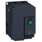
Schneider Electric Variable Speed Drive, ATV320, 1.5 kW, 380-500V, 3-Phase, with Heat Sink

Range of product: Altivar Machine ATV320
Product type: Variable speed drive
Product specific application: Complex machines
Variant: Standard version
You May Also Like:
 Schneider Electric Variable Speed Drive Altivar Machine ATV320, 5.5 kW, 380-500V, 3 Phases, CompactSpecial Price EGP 31,363 Regular Price EGP 57,023
 Schneider Electric Variable Speed Drive ATV320, 0.75 kW, 380-500V, 3 Phases, BookSpecial Price EGP 15,725 Regular Price EGP 28,591
 Schneider Electric Variable Speed Drive, Altivar Machine ATV320, 0.75 kW, 200-240V, 1 Phase, BookSpecial Price EGP 12,860 Regular Price EGP 23,381
 Schneider Electric Variable Speed Drive ATV320, 0.55 kW, 380-500V, 3 Phases, CompactSpecial Price EGP 13,506 Regular Price EGP 24,556
 Schneider Electric Variable Speed Drive ATV320, 4 kW, 380-500V, 3 Phases, CompactSpecial Price EGP 24,246 Regular Price EGP 44,084
 Schneider Electric Variable Speed Drive ATV320, 5.5 kW, 380-500V, 3 Phases, BookSpecial Price EGP 33,651 Regular Price EGP 61,184
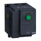 Schneider Electric Variable Speed Drive ATV320U15M2C, ATV320, 1.5 kW, 380-500V, 3-Phase, with Heat SinkSpecial Price EGP 15,205 Regular Price EGP 27,645
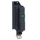 Schneider Electric Variable Speed Drive, ATV320, 2.2 kW, 200-240V, 1 Phase, BookSpecial Price EGP 18,170 Regular Price EGP 33,037
The ATV320U15N4B Variable Speed Drive is the ideal choice for controlling motor speed in various applications. It is known for its excellent performance and compact design, making it suitable for diverse industrial environments. It can deliver a power of up to 1.5 kW with an operating voltage range of 380 to 500V and operates in three phases, which makes it a reliable choice for a wide range of applications.
Key Features:
Excellent Performance: The ATV320U15N4B drive provides outstanding speed control performance, making it suitable for a wide range of industrial applications.
Multi-Phase Operation: This drive can operate with a power supply voltage ranging from 380 to 500V and functions with three phases, expanding its connectivity options.
Compact Design: It features a compact design that facilitates installation and integration in industrial environments.
Technical Specifications:
Product Type: Variable Speed Drive
Power: 1.5 kW
Voltage: 380-500V, 3-Phase
Compact Design: Yes
| Specifications | |
Main | |
| Range of Product | Altivar Machine ATV320 |
| Product or Component Type | Variable speed drive |
| Product Specific Application | Complex machines |
| Variant | Standard version |
| Format of the drive | Book |
| Mounting Mode | Cabinet mount |
| Communication Port Protocol | Modbus serial |
| CANopen | |
| Option card | Communication module, CANopen |
| communication module, EtherCAT | |
| communication module, Profibus DP V1 | |
| communication module, PROFINET | |
| communication module, Ethernet Powerlink | |
| communication module, EtherNet/IP | |
| communication module, DeviceNet | |
| [Us] rated supply voltage | 380...500 V - 15...10 % |
| Nominal output current | 4.1 A |
| Motor power kW | 1.5 kW heavy duty |
| EMC filter | Class C2 EMC filter integrated |
| IP degree of protection | IP20 |
| Complementary | |
| Discrete input number | ٧ |
| Discrete input type | STO safe torque off, 24 V DC1.5 kOhm |
| DI1...DI6 logic inputs, 24 V DC 30 V) | |
| DI5 programmable as pulse input 0…30 kHz, 24 V DC 30 V) | |
| Discrete input logic | Positive logic (source) |
| Negative logic (sink) | |
| Discrete output number | ٣ |
| Discrete output type | Open collector DQ+ 0…1 kHz 30 V DC 100 mA |
| Open collector DQ- 0…1 kHz 30 V DC 100 mA | |
| analogue input number | ٣ |
| Analogue input type | AI1 voltage 0...10 V DC 30 kOhm 10 bits |
| AI2 bipolar differential voltage +/- 10 V DC 30 kOhm 10 bits | |
| AI3 current 0...20 mA (or 4-20 mA, x-20 mA, 20-x mA or other patterns by configuration) 250 Ohm 10 bits | |
| analogue output number | ١ |
| Analogue output type | Software-configurable current AQ1 0...20 mA 800 Ohm 10 bits |
| Software-configurable voltage AQ1 0...10 V DC 470 Ohm 10 bits | |
| Relay output type | Configurable relay logic R1A 1 NO 100000 cycles |
| Configurable relay logic R1B 1 NC 100000 cycles | |
| Configurable relay logic R1C | |
| Configurable relay logic R2A 1 NO 100000 cycles | |
| Configurable relay logic R2C | |
| Maximum switching current | Relay output R1A, R1B, R1C resistive, cos phi = 1 3 A 250 V AC |
| Relay output R1A, R1B, R1C resistive, cos phi = 1 3 A 30 V DC | |
| Relay output R1A, R1B, R1C, R2A, R2C inductive, cos phi = 0.4 7 ms 2 A 250 V AC | |
| Relay output R1A, R1B, R1C, R2A, R2C inductive, cos phi = 0.4 7 ms 2 A 30 V DC | |
| Relay output R2A, R2C resistive, cos phi = 1 5 A 250 V AC | |
| Relay output R2A, R2C resistive, cos phi = 1 5 A 30 V DC | |
| Minimum switching current | Relay output R1A, R1B, R1C, R2A, R2C 5 mA 24 V DC |
| Method of access | Slave CANopen |
| 4 quadrant operation possible | TRUE |
| Asynchronous motor control profile | Voltage/frequency ratio, 5 points |
| Flux vector control without sensor, standard | |
| Voltage/frequency ratio - Energy Saving, quadratic U/f | |
| Flux vector control without sensor - Energy Saving | |
| Voltage/frequency ratio, 2 points | |
| Synchronous motor control profile | Vector control without sensor |
| Transient overtorque | 170…200 % of nominal motor torque |
| Maximum output frequency | 0.599 kHz |
| Acceleration and deceleration ramps | Linear |
| U | |
| S | |
| CUS | |
| Ramp switching | |
| Acceleration/deceleration ramp adaptation | |
| Acceleration/deceleration automatic stop with DC injection | |
| Motor slip compensation | Automatic whatever the load |
| Adjustable 0...300 % | |
| Not available in voltage/frequency ratio (2 or 5 points) | |
| Switching frequency | 2...16 kHz adjustable |
| 4...16 kHz with derating factor | |
| Nominal switching frequency | 4 kHz |
| Braking to standstill | By DC injection |
| Brake chopper integrated | TRUE |
| Line current | 6.5 A 380 V heavy duty) |
| 4.9 A 500 V heavy duty) | |
| Maximum Input Current per Phase | 6.5 A |
| Maximum output voltage | 500 V |
| Apparent power | 4.2 kVA 500 V heavy duty) |
| Network Frequency | 50-60 Hz |
| Relative symmetric network frequency tolerance | 5% |
| Prospective line Isc | 5 kA |
| Base load current at high overload | 1.5 A |
| Power dissipation in W | Fan 56.0 W 380 V 4 kHz |
| With safety function Safely Limited Speed (SLS) | TRUE |
| With safety function Safe brake management (SBC/SBT) | FALSE |
| With safety function Safe Operating Stop (SOS) | FALSE |
| With safety function Safe Position (SP) | FALSE |
| With safety function Safe programmable logic | FALSE |
| With safety function Safe Speed Monitor (SSM) | FALSE |
| With safety function Safe Stop 1 (SS1) | TRUE |
| With sft fct Safe Stop 2 (SS2) | FALSE |
| With safety function Safe torque off (STO) | TRUE |
| With safety function Safely Limited Position (SLP) | FALSE |
| With safety function Safe Direction (SDI) | FALSE |
| Protection type | Input phase breaks drive |
| Overcurrent between output phases and earth drive | |
| Overheating protection drive | |
| Short-circuit between motor phases drive | |
| Thermal protection drive | |
| Width | 1.77 in (45.0 mm) |
| Height | 12.80 in (325.0 mm) |
| Depth | 9.65 in (245.0 mm) |
| Net Weight | 5.51 lb(US) (2.5 kg) |
| Environment | |
| Operating position | Vertical +/- 10 degree |
| Product Certifications | CE |
| ATEX | |
| NOM | |
| GOST | |
| EAC | |
| RCM | |
| KC | |
| Marking | CE |
| ATEX | |
| UL | |
| CSA | |
| EAC | |
| RCM | |
| standards | IEC 61800-5-1 |
| Electromagnetic compatibility | Electrostatic discharge immunity test level 3 IEC 61000-4-2 |
| Radiated radio-frequency electromagnetic field immunity test level 3 IEC 61000-4-3 | |
| Electrical fast transient/burst immunity test level 4 IEC 61000-4-4 | |
| 1.2/50 µs - 8/20 µs surge immunity test level 3 IEC 61000-4-5 | |
| Conducted radio-frequency immunity test level 3 IEC 61000-4-6 | |
| Voltage dips and interruptions immunity test IEC 61000-4-11 | |
| Environmental class (during operation) | Class 3C3 according to IEC 60721-3-3 |
| Class 3S2 according to IEC 60721-3-3 | |
| Maximum acceleration under shock impact (during operation) | 150 m/s² at 11 ms |
| Maximum acceleration under vibrational stress (during operation) | 10 m/s² at 13...200 Hz |
| Maximum deflection under vibratory load (during operation) | 1.5 mm at 2...13 Hz |
| Permitted relative humidity (during operation) | Class 3K5 according to EN 60721-3 |
| Volume of cooling air | 2483.26 Gal/hr(US) (9.4 m3/h) |
| Overvoltage category | III |
| Regulation loop | Adjustable PID regulator |
| Speed accuracy | +/- 10 % of nominal slip 0.2 Tn to Tn |
| Pollution degree | 2 |
| Ambient air transport temperature | -13…158 °F (-25…70 °C) |
| Ambient air temperature for operation | 14…122 °F (-10…50 °C) without derating |
| 122…140 °F (50…60 °C) with derating factor |
| Weight | 2.500000 |
|---|---|
| Brand | Schneider Electric |
| Model | ATV320U15N4B |
| Width [cm] | 4.5 |
| Height [cm] | 32.5 |
| Range | ATV320 |
| Family | IDVSD |
The information below is required for social login
Sign In
Create New Account