

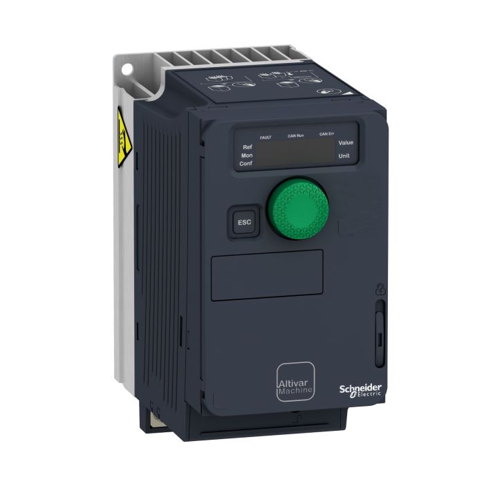
Schneider Electric Variable Speed Drive ATV320, 0.18 kW, 200-240V, 1 Phase, Compact

Range of product: Altivar Machine ATV320
Product type: Variable speed drive
Product specific application: Complex machines
Variant: Standard version
You May Also Like:
 Schneider Electric Variable Speed Drive Altivar Machine ATV320, 5.5 kW, 380-500V, 3 Phases, CompactSpecial Price EGP 31,363 Regular Price EGP 57,023
 Schneider Electric Variable Speed Drive ATV320, 0.75 kW, 380-500V, 3 Phases, BookSpecial Price EGP 15,725 Regular Price EGP 28,591
 Schneider Electric Variable Speed Drive, Altivar Machine ATV320, 0.75 kW, 200-240V, 1 Phase, BookSpecial Price EGP 12,860 Regular Price EGP 23,381
 Schneider Electric Variable Speed Drive ATV320, 0.55 kW, 380-500V, 3 Phases, CompactSpecial Price EGP 13,506 Regular Price EGP 24,556
 Schneider Electric Variable Speed Drive ATV320, 4 kW, 380-500V, 3 Phases, CompactSpecial Price EGP 24,246 Regular Price EGP 44,084
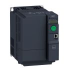 Schneider Electric Variable Speed Drive ATV320, 5.5 kW, 380-500V, 3 Phases, BookSpecial Price EGP 33,651 Regular Price EGP 61,184
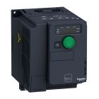 Schneider Electric Variable Speed Drive ATV320U15M2C, ATV320, 1.5 kW, 380-500V, 3-Phase, with Heat SinkSpecial Price EGP 15,205 Regular Price EGP 27,645
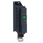 Schneider Electric Variable Speed Drive, ATV320, 2.2 kW, 200-240V, 1 Phase, BookSpecial Price EGP 18,170 Regular Price EGP 33,037
The ATV320U02M2C Variable Speed Drive ATV320 is designed for applications that require precise control of motor speed in a compact form. With a power rating of 0.18 kW and compatibility with 200-240V single-phase power systems, this drive is suitable for a wide range of applications. Its compact design allows for easy integration, making it an ideal choice for motor control.
Key Features:
Precise Control: This drive allows for precise control of motor speed, making it suitable for various applications.
Compatibility: Designed for use with 200-240V single-phase power systems, ensuring versatility in different settings.
Compact Design: The compact form factor allows for easy installation and space-saving.
Technical Specifications:
Product Type: Variable Speed Drive
Power Rating: 0.18 kW
Voltage Rating: 200-240V, 1 Phase
Compact Design: Yes
| Specifications | |
Main | |
| Range of Product | Altivar Machine ATV320 |
| Product or Component Type | Variable speed drive |
| Product Specific Application | Complex machines |
| Variant | Standard version |
| Format of the drive | Compact |
| Mounting Mode | Wall mount |
| Communication Port Protocol | Modbus serial |
| CANopen | |
| Option card | Communication module, CANopen |
| communication module, EtherCAT | |
| communication module, Profibus DP V1 | |
| communication module, PROFINET | |
| communication module, Ethernet Powerlink | |
| communication module, EtherNet/IP | |
| communication module, DeviceNet | |
| [Us] rated supply voltage | 200...240 V - 15...10 % |
| Nominal output current | 1.5 A |
| Motor power kW | 0.18 kW heavy duty |
| EMC filter | Class C2 EMC filter integrated |
| IP degree of protection | IP20 |
| Complementary | |
| Discrete input number | ٧ |
| Discrete input type | STO safe torque off, 24 V DC1.5 kOhm |
| DI1...DI6 logic inputs, 24 V DC 30 V) | |
| DI5 programmable as pulse input 0…30 kHz, 24 V DC 30 V) | |
| Discrete input logic | Positive logic (source) |
| Negative logic (sink) | |
| Discrete output number | ٣ |
| Discrete output type | Open collector DQ+ 0…1 kHz 30 V DC 100 mA |
| Open collector DQ- 0…1 kHz 30 V DC 100 mA | |
| analogue input number | ٣ |
| Analogue input type | AI1 voltage 0...10 V DC 30 kOhm 10 bits |
| AI2 bipolar differential voltage +/- 10 V DC 30 kOhm 10 bits | |
| AI3 current 0...20 mA (or 4-20 mA, x-20 mA, 20-x mA or other patterns by configuration) 250 Ohm 10 bits | |
| analogue output number | ١ |
| Analogue output type | Software-configurable current AQ1 0...20 mA 800 Ohm 10 bits |
| Software-configurable voltage AQ1 0...10 V DC 470 Ohm 10 bits | |
| Relay output type | Configurable relay logic R1A 1 NO 100000 cycles |
| Configurable relay logic R1B 1 NC 100000 cycles | |
| Configurable relay logic R1C | |
| Configurable relay logic R2A 1 NO 100000 cycles | |
| Configurable relay logic R2C | |
| Maximum switching current | Relay output R1A, R1B, R1C resistive, cos phi = 1 3 A 250 V AC |
| Relay output R1A, R1B, R1C resistive, cos phi = 1 3 A 30 V DC | |
| Relay output R1A, R1B, R1C, R2A, R2C inductive, cos phi = 0.4 7 ms 2 A 250 V AC | |
| Relay output R1A, R1B, R1C, R2A, R2C inductive, cos phi = 0.4 7 ms 2 A 30 V DC | |
| Relay output R2A, R2C resistive, cos phi = 1 5 A 250 V AC | |
| Relay output R2A, R2C resistive, cos phi = 1 5 A 30 V DC | |
| Minimum switching current | Relay output R1A, R1B, R1C, R2A, R2C 5 mA 24 V DC |
| Method of access | Slave CANopen |
| 4 quadrant operation possible | TRUE |
| Asynchronous motor control profile | Voltage/frequency ratio, 5 points |
| Flux vector control without sensor, standard | |
| Voltage/frequency ratio - Energy Saving, quadratic U/f | |
| Flux vector control without sensor - Energy Saving | |
| Voltage/frequency ratio, 2 points | |
| Synchronous motor control profile | Vector control without sensor |
| Transient overtorque | 170…200 % of nominal motor torque |
| Maximum output frequency | 0.599 kHz |
| Acceleration and deceleration ramps | Linear |
| U | |
| S | |
| CUS | |
| Ramp switching | |
| Acceleration/deceleration ramp adaptation | |
| Acceleration/deceleration automatic stop with DC injection | |
| Motor slip compensation | Automatic whatever the load |
| Adjustable 0...300 % | |
| Not available in voltage/frequency ratio (2 or 5 points) | |
| Switching frequency | 2...16 kHz adjustable |
| 4...16 kHz with derating factor | |
| Nominal switching frequency | 4 kHz |
| Braking to standstill | By DC injection |
| Brake chopper integrated | TRUE |
| Line current | 3.4 A 200 V heavy duty) |
| 2.8 A 240 V heavy duty) | |
| Maximum Input Current per Phase | 3.4 A |
| Maximum output voltage | 240 V |
| Apparent power | 0.7 kVA 240 V heavy duty) |
| Network Frequency | 50-60 Hz |
| Relative symmetric network frequency tolerance | 5% |
| Prospective line Isc | 1 kA |
| Base load current at high overload | 6.9 A |
| Power dissipation in W | Self-cooled 17.0 W 200 V 4 kHz |
| With safety function Safely Limited Speed (SLS) | TRUE |
| With safety function Safe brake management (SBC/SBT) | FALSE |
| With safety function Safe Operating Stop (SOS) | FALSE |
| With safety function Safe Position (SP) | FALSE |
| With safety function Safe programmable logic | FALSE |
| With safety function Safe Speed Monitor (SSM) | FALSE |
| With safety function Safe Stop 1 (SS1) | TRUE |
| With sft fct Safe Stop 2 (SS2) | FALSE |
| With safety function Safe torque off (STO) | TRUE |
| With safety function Safely Limited Position (SLP) | FALSE |
| With safety function Safe Direction (SDI) | FALSE |
| Protection type | Input phase breaks drive |
| Overcurrent between output phases and earth drive | |
| Overheating protection drive | |
| Short-circuit between motor phases drive | |
| Thermal protection drive | |
| Width | 2.83 in (72.0 mm) |
| Height | 5.63 in (143.0 mm) |
| Depth | 4.29 in (109.0 mm) |
| Net Weight | 1.76 lb(US) (0.8 kg) |
| Environment | |
| Operating position | Vertical +/- 10 degree |
| Product Certifications | CE |
| ATEX | |
| NOM | |
| GOST | |
| EAC | |
| RCM | |
| KC | |
| Marking | CE |
| ATEX | |
| UL | |
| CSA | |
| EAC | |
| RCM | |
| standards | IEC 61800-5-1 |
| Electromagnetic compatibility | Electrostatic discharge immunity test level 3 IEC 61000-4-2 |
| Radiated radio-frequency electromagnetic field immunity test level 3 IEC 61000-4-3 | |
| Electrical fast transient/burst immunity test level 4 IEC 61000-4-4 | |
| 1.2/50 µs - 8/20 µs surge immunity test level 3 IEC 61000-4-5 | |
| Conducted radio-frequency immunity test level 3 IEC 61000-4-6 | |
| Voltage dips and interruptions immunity test IEC 61000-4-11 | |
| Environmental class (during operation) | Class 3C3 according to IEC 60721-3-3 |
| Class 3S2 according to IEC 60721-3-3 | |
| Maximum acceleration under shock impact (during operation) | 150 m/s² at 11 ms |
| Maximum acceleration under vibrational stress (during operation) | 10 m/s² at 13...200 Hz |
| Maximum deflection under vibratory load (during operation) | 1.5 mm at 2...13 Hz |
| Permitted relative humidity (during operation) | Class 3K5 according to EN 60721-3 |
| Overvoltage category | III |
| Regulation loop | Adjustable PID regulator |
| Speed accuracy | +/- 10 % of nominal slip 0.2 Tn to Tn |
| Pollution degree | 2 |
| Ambient air transport temperature | -13…158 °F (-25…70 °C) |
| Ambient air temperature for operation | 14…122 °F (-10…50 °C) without derating |
| 122…140 °F (50…60 °C) with derating factor | |
| Ambient Air Temperature for Storage | -13…158 °F (-25…70 °C) |
| Weight | 1.073000 |
|---|---|
| Brand | Schneider Electric |
| Model | ATV320U02M2C |
| Width [cm] | 7.2 |
| Height [cm] | 14.3 |
| Range | ATV320 |
| Family | IDVSD |
The information below is required for social login
Sign In
Create New Account